Carbon dioxide liquefaction and underground injection apparatus
Client / Market
- CO2 underground injection facility manufacturer, CO2 utilizing industry
Necessity of this Technology
- With ocean storage, CO2 emitted from the earth is expected to be stored for 500
years by releasing CO2 below 3,000 m-deep ocean floor, but due to safety issues
including problems with ecosystems and ocean acidification, this is prohibited by
international laws. Surface storage method takes CO2 to react to addible mineral
such as magnesium or potassium for chemical reaction, but there is an issue of the
cost for chemical reaction and the treatment of resulting chemical products.
- Cooling for CO2 liquefaction requires a great energy consumption, and for
underground injection, it is heated up to a high-pressure supercritical state, which
also requires extensive energy. It is problematic to consume a lot of energy for
liquefaction and storage of CO2, even though CO2 sequestration is required for
environment preservation.
Technical Differentiation
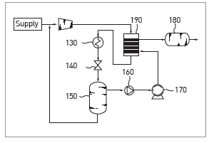
- By resupplying the gas CO2 that went through the gas-liquid separator with a
compressor, energy required for liquefaction is reduced.
- By adopting an injection part with injection pump and heater, CO2 is relatively easily
made into supercritical state for underground injection.
- The injection part includes a high-pressure pump to prevent cavitation.
- By adopting a heat exchanger for heat exchange between CO2 from the injection
pump and CO2 from the compressor, energy consumption for CO2 liquefaction and
storage is significantly reduced.
- The heat exchanger is located between the injection pump and the heater to heat
CO2 with the heat exchanger and then again with the heater to reduce energy
consumption for CO2 storage.
- It is a CO2 liquefaction and underground injection apparatus that saves energy
through heat exchange between CO2 liquefied for transportation and CO2 heated into
the supercritical state for underground injection.
Excellence of Technology
- It is composed of the gas-liquid separator to separate CO2 that went through the feed, compressor, and cooler into gas CO2 and liquid CO2, injection part that converts liquid CO2 into supercritical CO2 for underground injection, and compressor where gas CO2 is resupplied for recompression.
Current Intellectual Property Right Status
PATENT
- CO2 Liquefaction and Underground Injection Apparatus (KR1399442)
KNOW-HOW
- System design and engineering technology
- Flow mixing, heating apparatus design technology
- CO2 heat exchanger design technology
- CO2 injection turbo pump technology
|